TICRA Tools 21.0 is released!
We are happy to announce that TICRA Tools 21.0 is released. With this release, the user will experience many new features and enhancements across the products; GRASP, ESTEAM, POS, CHAMP 3D and QUPES.
In TICRA Tools 21.0, users of any of the products in TICRA Tools will experience a much easier workflow during data visualisation and postprocessing.
Easy analysis and comparison of plot styles
With the introduction of Plot Styles, the user can easily define and apply a given plot layout to new sets of data. Combined with the new analysis tools available in 2D and grid plots, this makes it easy to analyse and compare results for different antenna and waveguide geometries.
By combining the Plot Styles with the new Text Field Insertion it is also possible to automatically generate informative text strings for the plots.
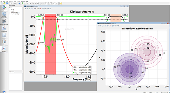
Add markers and illustrations to 2D plots
In 2D plots it is now possible to add a number of different markers and illustrations of features in the plot. Markers can be placed at fixed values along the x axis to quickly let the user extract key values from a data set or inserted as analysis lines to give tabulated information about the value of all lines at a specific value along the x or y axes of the plot.
It is also possible to mark areas of interest with different types of coloured regions. And for radiation patterns there are the options for inserting beamwidth and sidelobe-level markers in the plots to quickly extract these critical parameters.
Select and plot data from multiple grids
The plot feature for data in grid format has been enhanced in several ways. First and foremost, the contour-plot facility has been enhanced with many useful features from TICRA’s SATSOFT. The enhancements include filled contours, contours with different colour and line styles for the individual beams plotted in the same plot, and a slew of other enhancements.
Combined with the new Plot Style functionality, it is much more convenient for the user to investigate both single and multibeam configurations in the Results Tab of TICRA Tools.
In addition to the new contour features, there are new markers available for grid plots, including automatic location of local minima and maxima in the data.
Convenient reporting of pattern characteristics
A number of commands for the analysis of radiation patterns have been added to TICRA Tools. These includes analyses of the sidelobe level, aperture efficiency, and beam efficiency. All pattern characteristics are presented in the Results Tab in tabulated format which makes it convenient to sort the results and copy them to external programs for reporting and presenting.
New features in GRASP
Set up torus reflectors easily
For GRASP users, TICRA Tools 21.0 provides easy definition of torus reflectors as a new torus surface has been added.
Normalise amplitude of excitation coefficients in arrays
It is now possible to automatically normalise the amplitude of excitation coefficients in arrays. This makes it more convenient to model large arrays and get the correct directivity.
Analyse power in azimuthal modes of imported patterns
In previous versions of TICRA Tools, imported feed patterns in Tabulated Pattern objects were analysed and warnings were given to the user if the power distribution in the polar modes indicated that the pattern was not sufficiently densely sampled. In this version, the analysed has been extended to also analyse the azimuthal modes in the imported patterns.
Visit the product page for GRASP.
Calculate the C/I pattern between multiple beams
A new command has been implemented for POS user. It allows the user to calculate C/I in either cuts or grids. The new command operates of field storage objects, and it is thus possible to store the individual beams in smaller regions while calculating the C/I over the entire coverage area.
Visit the product page for POS.
New features in CHAMP 3D
Calculate Conductor Losses for devices analysed with MoM
The Method of Moments (MoM) analysis engine applies to all devices in CHAMP 3D, making it possible for the user to calculate conductor losses for all waveguides and apertures. This gives the user the possibility to analyse metallic feeds and feeding network more accurately and thus to obtain better agreement with measurements.
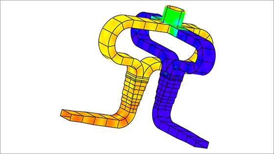
Calculate currents on waveguide devices in plot of 3D Surface Currents
Another new feature is the possibility to calculate and plot the induced surface current densities on the involved waveguide devices that are analysed with MoM. The plotted currents give the user better physical insight into the analysed device that can help to locate possible errors and to improve the design.
Easy control of location in exported device MoM mesh
CHAMP 3D allows the user to easily control the location of an exported device MoM mesh by specifying where a particular waveguide port should be located when generating the MoM mesh. Also, the user has the possibility to view a list of the location and orientation of the internal waveguide ports in the device. These new features will make it easier to adjust the exported mesh to the requirement needed for the further processing and analysis of the mesh.
Additionally, a circular waveguide mitered bend device has been added to CHAMP 3D, allowing the user to analyse and design a mitered bend for circular waveguides. Hence, if the user wants to analyse such a device, the built-in version can be used instead of applying a CAD-file description. Also, this allows for optimisation of the circular mitered bend, which is not possible when using the CAD-file representation.
Visit the product page for CHAMP 3D.
Finally, this release offers several enhancements and bugfixes across all products in TICRA Tools that users will find useful in their daily work with antenna design.
With a valid Technical Support and Maintenance contract you can download TICRA Tools. 21.0 on our support site.